
TM 5-3820-246-14&P
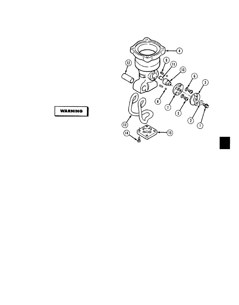
(7) Install end plate (15) and four screws (14).
(8) Install tool holder (13) and spring pin (12).
(9) Install selector pin (11) and rotor (10) using
a small amount of grease to hold in front
end (4).
NOTE
Check to ensure that selector pin engages
groove in internal shaft before proceeding.
(10) Install two springs (9) in front end (4).
(11) Install two balls (8) in stopper plate (7).
Adhesives, solvents, and sealing
compounds can burn easily, can give off
harmful vapors, and are harmful to skin
and clothing. To avoid injury or death,
keep away from open fire and use in a well-
ventilated area. If adhesive, solvent, or
sealing compound gets on skin or clothing,
wash immediately with soap and water.
NOTE
Ensure balls and springs are aligned.
(12) Apply loctite to four screws (5) and install stopper plate (7) with four lockwashers (6) and four screws.
Tighten to 120 lb-in (14 N.m).
NOTE
Mode selector and front end must be aligned so that internal shaft is engaged with notches in end plate
when "B" on selector mode is up.
(13) Install mode selector (3), retaining plate (2), and screw and washer (1) with 6 mm socket head screw key.
NOTE
Follow-on maintenance: Install front end (para 4-22).
END OF TASK
5-31/(5-32 blank)
