TM 5-3895-376-14&P
4-26. CLUTCH ASSEMBLY MAINTENANCE INSTRUCTIONS - Continued
4.
Unhook the springs (5) from the brake shoes (3),
from the ball bearing installed in the clutch hous-
and separate the brake shoes and weights,
ing (4).
5.
Clean the weights and springs off with a clean
rag.
5.
Using snap ring plier, remove the inner retaining
ring (5).
6.
Install replacement brake shoes (3) over
weights (4) and hook two springs on each side.
6.
Remove the four screws (6), outer and inner
shields (7 and 8).
7.
Install the assembled brake shoes, weights and
springs into the clutch housing by pulling the
brake shoes apart and seating the weights and
brake shoes around the center shaft.
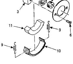
7.
Separate assembled brake shoes (10),
weights (11), and springs (9) from the center
shaft (3).
8.
8.
Install the outer shield (2) and secure with two
screws (1).
Remove the four springs (9) and separate the
brake shoes (10) and weights (11).
9.
10.
Remove threaded plug (12).
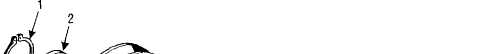
1.
Using snap ring plier, remove the outer retaining
ring (1).
Using snap ring plier, remove the retaining
ring (13) from inside the clutch housing (4).
2.
Pry the dust cover (2) from bore of clutch hous-
ing (4).
3.
Place the clutch assembly on blocking (approxi-
mately 4 inches (102 mm) high) that supports the
pulley flange of the clutch assembly with the cen-
ter shaft (2) hanging down.
4.
With wood block or brass drift, tap on the end of
the center shaft (3) to drive the shaft assembly
4-45